 Some ribbon cable, a few gates , diodes resistors and some awful code ;)
Some ribbon cable, a few gates , diodes resistors and some awful code ;)
(click on the image above for bigger view)
DISCLAIMER:
THE INFORMATION ON THIS AND RELATED PAGES/FILES IS PROVIDED "AS IS" WITHOUT WARRANTY OF ANY KIND, EITHER EXPRESSED OR IMPLIED, INCLUDING, BUT NOT LIMITED TO, THE IMPLIED WARRANTIES OF FITNESS FOR A PARTICULAR PURPOSE.
THE ENTIRE RISK AS TO THE ABILITY TO USE ANY OF THE INFORMATION PROVIDED HERE TO INTERFACE WITH THE REMOTE PORT OF A SONY PORTABLE PLAYSTATION (PSP) IS WITH YOU. SHOULD ANY OF THE INFORMATION PROVE INACCURATE OR ERRONEOUS, THE AUTHOR OF THIS PAGE IS NOT LIABLE AND YOU ASSUME THE COST OF ALL NECESSARY SERVICING, REPAIR OR CORRECTION.
DESCRIPTION:
o Overview
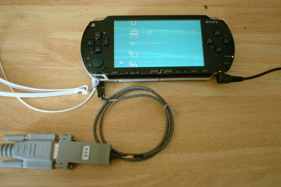
As already revealed here and here, the Remote port of the PSP is in fact a serial port, and the remote is being handled through a standard RS232 protocol, albeit using [0,+2.5V] voltage instead of [-12,+12V]. Therefore the question is; is it possible to connect the PSP remote port to a PC serial port? The answer is yes!
Of course, you can NOT plug a PSP directly into a PC serial port (unless you want to fry it beyond repairs), but with a simple serial line converter this is no trouble at all, and you can then exploit a standard serial port out of the PSP.
The purpose of this page is to explain how to do this.
o Why is having serial communications between a PSP and a PC an interesting feat?
This is interesting because it can provide us with a very wide array of facilities:
- Debug output for application development:
This is already happening - Check out the excellent PSPLink by TyRaNiD!
- Serial console for any Linux port (a must have device indeed!) or any other applications
- The serial protocol is a simple, well known and robust protocol, with loads of existing applications ready to be used. You could even use a PSP for dial up access or GPS!
- Hijacking the UART4 PSP driver to use the Remote UART might give us access to the low level debug functions of the PSP without the need to tear it apart in order to access the internal UART4
Also:
- The remote is a very optional device for the PSP => it can be used for other purposes (eg. debug) without interfering with standard operations (USB, WiFi, ...)
- As a serial device, IRDA could be used as well, but not everybody has an IRDA receiver. On the other hand, almost every computer out there has a serial port (sorry Mac users - this is the one thing that Apple did get wrong!)
- The cable is very inexpensive/simple to build (see below), and not doubt someone out there will be selling ready made cables for the PSP at some stage
- Rumoured additional capabilities of the Remote Port like re-flash (this is very doubtful, but who knows...)
- The Remote driver is probably the best driver to experiment with for development (low footprint, simple, loads of serial code samples out there)
Of course, at the moment, the only use we have for this serial port is to emulate the PSP remote, but this is likely to change in the future.
o So what next?
- Reverse engineering of the sceHP_Remote_Driver to see if there are additional features to standard remote operations
- Unload of the sceHP_Remote_Driver and replacement with our own custom serial driver
- Hijack the Uart4 driver and replace it by an equivalent driver using the Remote Port
- Linux on the PSP! :D
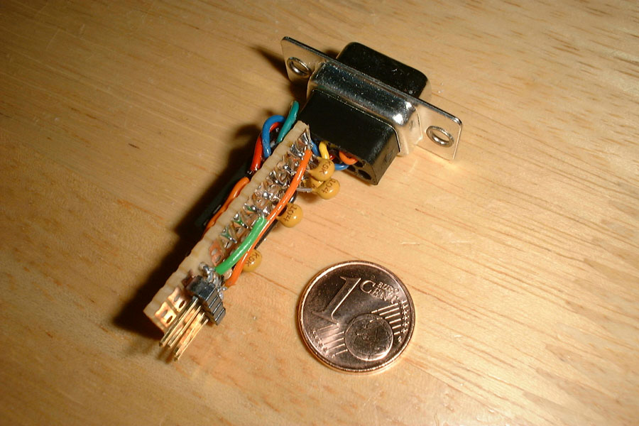
THE DEVICE:
o Details:
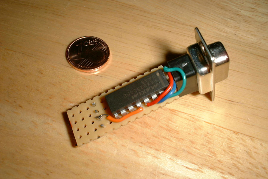
Various IC manufacturers do provide serial line voltage converters. In this montage we use a MAX3232 serial line converter, which, though listed for voltages above +3.0V, handles the +2.5V signals of the PSP just fine. Such a montage uses a handful of capacitors for the charge pump, but that's really all there is to it, therefore it is very simple and inexpensive to build - Anybody can build one.
o Diagram:
- Click on the image below to access the schematics (PDF)
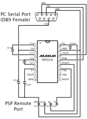
- Because the PSP can switch power off on the serial line, we want to have a way to check if our device is powered or not. To this effect we use the V+ output of the MAX3232 which we connect to the CTS pin of the RS232 connector (Of course, using the DSR pin would have been preferable, but the DB9 <-> RJ45 adapters that we use don't have this pin readily available).
o List of components:
- 5 x 0.1 uF ceramic capacitors
- 1 x MAX3232CPE - If you're going to build this montage, make sure you get the DIP version of the MAX3232 (= MAX3232CPE). Soldering SSOP or TSSOP by hand is simply NO FUN!
- Connectors (eg. DB9 female), cables, development PCB, etc.
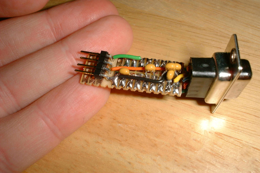
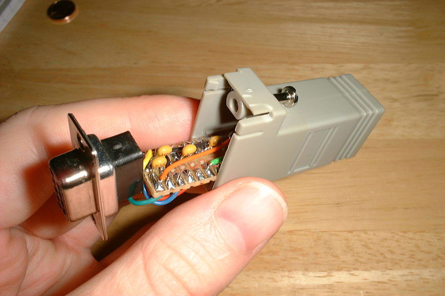
o Building the device:
I strongly advise getting your hands on one of these DB9<->RJ45 serial adapters pictured below (click on the image for bigger picture):
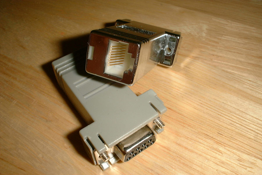
Because our serial converter is such a small montage, it is actually possible to fit it perfectly into one of these adapters. If you pry open one of these adapters (one notch above the RJ45 part and 4 for the DB9 plate), you will find that the RJ45 part slides into the DB9 housing, and it is the perfect size to fit small sliding PCB.
The DB9 part usually only has cabling for RxD, TxD, CTS, RTS and GND, so just cut the RJ45 part out and keep RTS as much as you can, since we will not be using it at all (double
check that you are indeed cutting RTS and not CTS!). Keep about 2-3 cm of the other connectors.
On the opposite hand of the PCB, you can use a right angle 4 ways 2.54 mm Molex connector. If you remove the comb structure of the RJ45 part from the socket (it's all plastic), the molex
connector should slide easily in place.
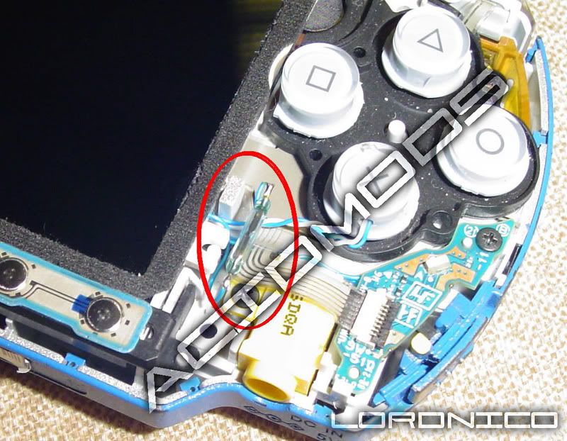
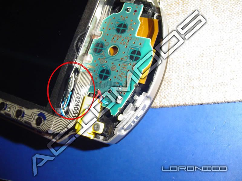
Below are pictures of the insides of the device (click on each image for bigger view):
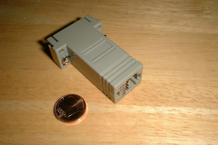
The finished device (click on the image for bigger picture):
CABLE AND CONNECTORS:
The interest of using a 2.54 mm Molex connector is that you can then use a standard 4 ways Analog CD - Audio Card cable to connect to the PSP. The only problem is that you need a cable with 4 actual connectors. Manufacturers are going so cheap these days that they are using 3 conductors instead of 4, so finding a proper cable can be a bit of a pain. Of course, you can always build your own cable, but the advantage of using an Audio Card cable is that you can easily reorganize the crimp connectors at each end, instead of having to fit those yourselves.
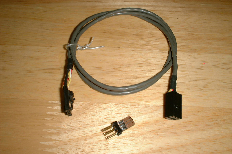
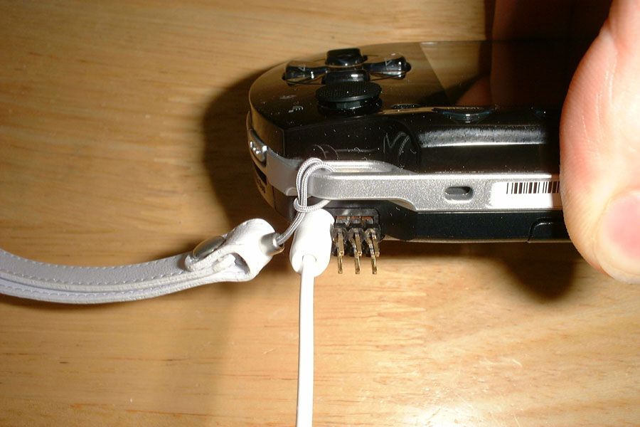
On the PSP end, you will obviously need to build a custom remote connector (the small part with 6 pins in the picture above). To achieve this, you can cut a double sided copper PCB into shape, using the original remote connector as guide. Then you can draw the 6 contacts with a cutter or any sharp object. Make sure you have a tight fit, and plug the PCB in place a few times before scratching the copper out, as this should leave very visible contact marks. Thoroughly check that each contact is isolated from the others before using the connector.
On the other end, you should be able to solder a 2.54 mm Molex 6 ways/dual row connector.
Before soldering, make sure that you leave enough room to be able to connect the headphones connector on the left side: Remember, the audio connector MUST be plugged in for the remote port to be powered!
Once you have the Molex dual row connector soldered in, you can use a 6 ways/double row housing to fit your audio cable in there - easy! ;)
SOFTWARE PSP REMOTE FOR LINUX: PSP_REMOTE v1.00

(click on image for bigger view)
psp_remote v1.00 is a sample Linux program that emulates the PSP Remote on a PC. It is meant to be used with the PSP Serial Converter device above. You need to be root to run it and have the ncurses library installed (any decent distribution of Linux should have it)
This program simply reads a numeric key and sends the associated PSP Remote code. It is more a proof of concept for serial communications between a PC and a PSP than anything else.
For more information on the PSP Remote protocol, have a look at the ps2dev.org thread or Marcus' page.
This program was compiled and tested on Slackware 10.0.
Download: psp_remote_v1.00.tgz

First i want to say, i am not responsible for any damage to your phone, expressed or implied, simply because this is a diy tutorial. USE THIS TUTORIAL AT YOUR OWN RISK!
That being said, let's get on with it.
I want to thank pinouts.ru for having a vast amount of information regarding pinouts for many items. hopefully you will be able to find the information you need.
I also want to thank bitpim.org for having the software needed to access my phone. With it you can transfer your phone book, pictures, and even custom made ring tones, along with other stuff.
I did this hack for two reasons, first, i didnt want to buy a usb cable for my phone. call me "cheap" but i did not see a reason to spend $30-$50 on a cable that i wouldnt use that often. second, theres no reason for me to spend $15/month for internet access on my phone, when i am only spending $10/mo for service. but still i wanted the freedom to take pictures with the phone and still be able to get the pictures off of it.
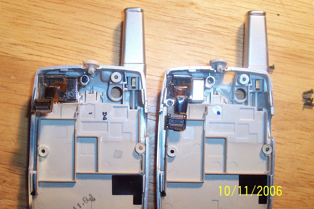
What you will need:


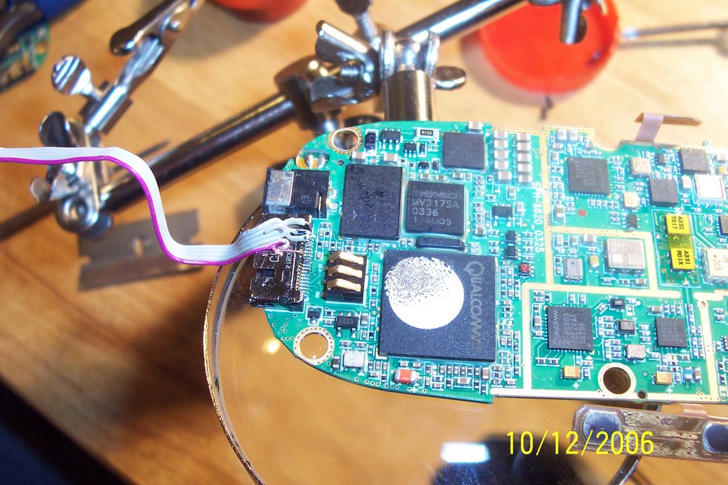
 de-soldered the usb jack to use in my phone
 carefully solder the wires to the jack. on mine i wanted to use the red wire as my the #1 pin for easier wiring, but when i double checked it, i wired it backwards, so now my red wire is the #4 wire.
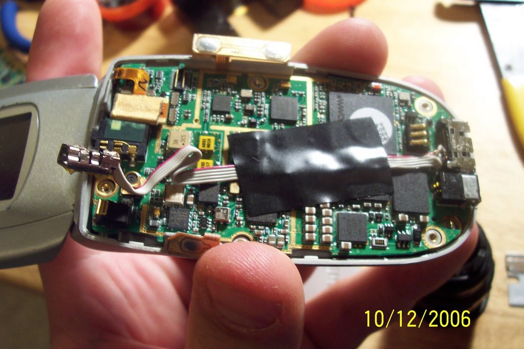
 once you get your usb cable ready we move to the fun part
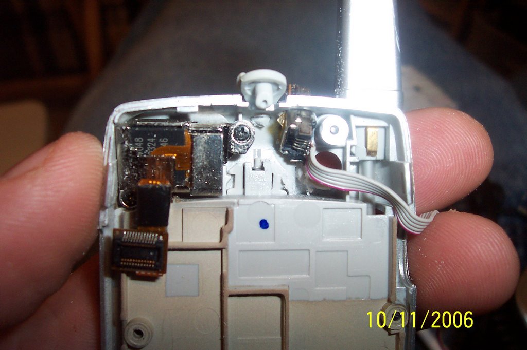

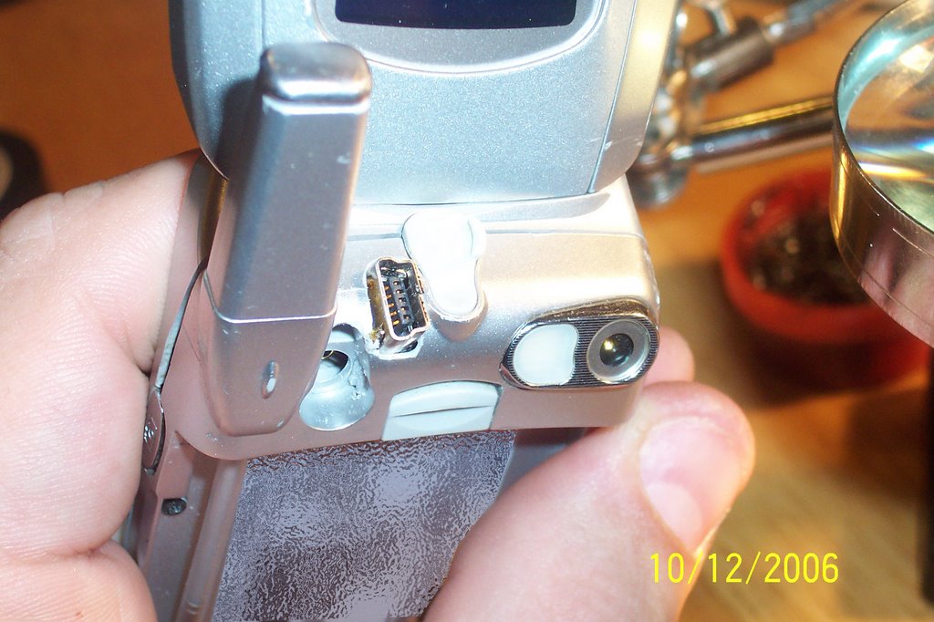
 this is why i ground it down. (those three connectors in the foreground connect to the battery pack), pretty tiny, eh

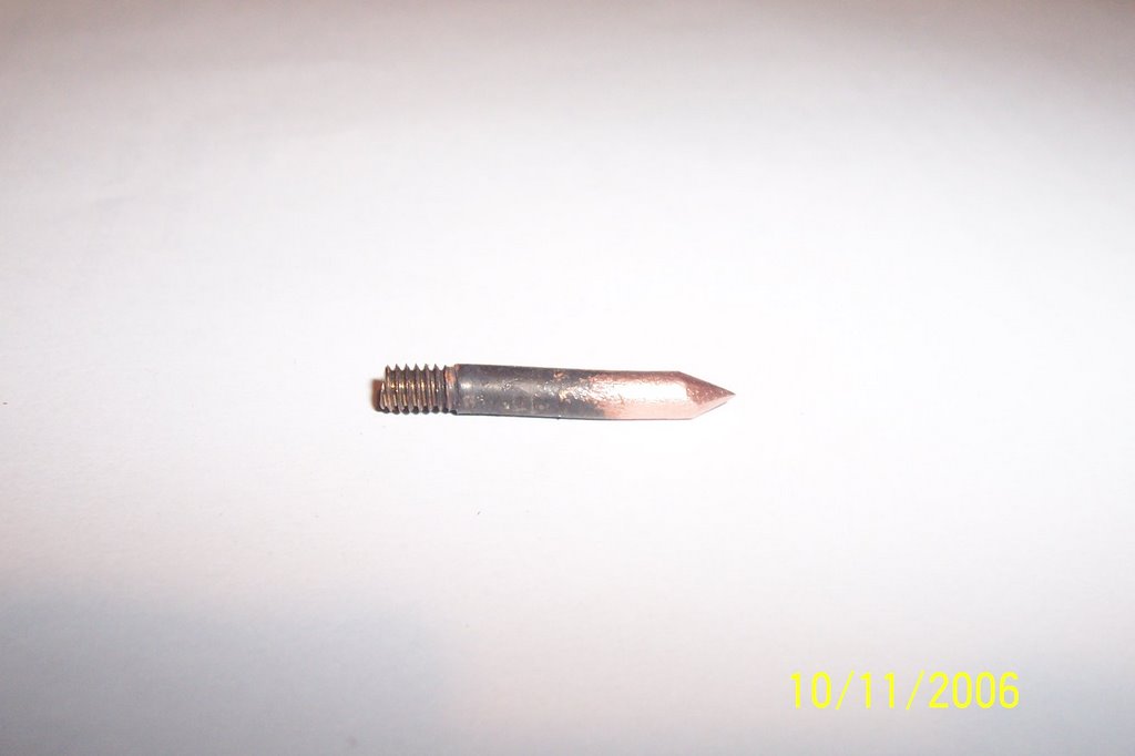
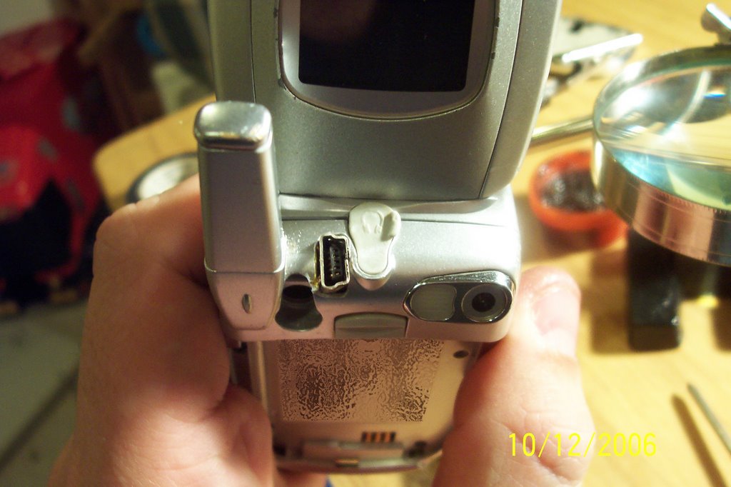 i took this picture to show that it still functions. hope yours comes out just as nice or better


Step 3
i will be using nero 5.x in my demonstration. nero 6 or other cd burning programs should work as long as they will burn in mode2/xa & iso9660 level 2.
1) first, open nero.
it might start up with the wizard, close the wizard

2) you need to create a "CD-ROM (ISO) [1], make sure its not multisession [2], and then you need to click the "ISO"[3] tab.

3) once you've clicked the "ISO" tab it will bring up this window.
make sure its "ISO Level 2" (1), make sure it set to "Mode 2/ XA"(2), make sure the character set is "ISO 9660"(3) & then click "New"
also make sure the "Relax ISO Restrictions" setting at the bottom are the same as the picture.

4) in the file browser go to "my computer" the "C:" drive, and the "MC" folder, highlight all the files except "titleman.exe" and drag them to the other side
(as indicated in the picture), then click the burn icon (in the little red box.. or just click file\write cd)

5) it will now bring up the "Write CD" window in nero, make sure you're on the "Burn" tab, and then all your settings reflect mine.
your cd burner may burn faster or slower than 16x (as indicated in my picture). once all your settings reflect the picture below, click "Write".
make sure you have a blank cd-r in your cd burner

you have now completed burning your installation cd-r.
Installing the HDL/memory card exploit
now we need to install the HDL/memory card exploit.
you need a way to boot the cd-r you just created. I've got a modchip in my PS2, and it worked just fine. If you can't boot a CDR, take your CDR and your mem card to a friend who does have a PS2 with a modchip.
insert the memory card with at least 600k free space in to memory card port 1 (remove anything in memory card port 2)
just insert the CDR in to your PS2 and boot it up, and it will begin the installation.
which should look like this;

(it will then proceed to copy files to your memory card)
and if all went well, you should see this screen:

if the installation failed, either your memory card is bad or you dont have enough room on the memory card. try a different memory card.
or you're using a 3rd party memory card (non-sony). always use official sony hardware (except HDD), the rest of the shit sucks.
Now remember you only need to do this once. With this done, read on to find out how to get everything working!
Booting HDLoader
now comes the fun part.. all your hardwork has finally paid off and you get to enjoy HD Loader in all its glory.
You'll need to make sure:
With all this done, boot up your PSX game. You will see HDLoader load up. You will need to do this every time you want to play games from your HDD.
If this is the first time you've used HDLoader on the HDD, it will ask you if you want to format it. Say YES.
Remember that you can't use this HD for anything else but PS2 games, unless you format it again in your computer.
BE SURE THERE'S NOTHING YOU WANT/NEED ON THE HDD. IT WILL BE LOST.
Once it is formatted (you only need to do that once), you will see a screen like this one:

(As you can see I've got a few games installed)
Click on Convert in the menu, insert a PS2 game, follow the prompts and it'll get installed to the HDD. Once the game is installed, select it in the list, and press X to load/play it!